
You've got the posts standing, the beam lifted into place, and a handful of screws already started. Then the frame moves when you push it, the beam refuses to sit squarely in the cap, or the inspector points out that the connection doesn't provide a complete load path. That's usually not a lumber problem. It's a post to beam connector problem, often made worse by the wrong finish or an incompatible fastener package.
Introduction to Post to Beam Connectors and Why They Matter
A post to beam connector transfers forces between two members that meet at a critical point in the structure. On a deck, the beam carries floor framing into the posts. On a pergola, the connector keeps the header seated and helps control movement. On a fence or guardrail, the hardware can help stabilise the assembly against forces that a simple toe-nailed joint won't reliably handle.
A proper connection creates a positive load path. Vertical load travels from the beam into the post, while the connection also resists uplift and lateral displacement. Toe-nails, a few general-purpose screws, or a bolt placed without regard to edge distance may hold the pieces together during assembly, but they don't automatically provide the engineered restraint a deck requires.
Field rule: If the beam can lift, rotate, slide, or pull away from the post without relying on friction alone, the connection needs deliberate positive attachment.
I've seen low pergolas tolerate improvised framing that would be unacceptable on a deck. I've also seen a seemingly heavy bracket fail because its holes didn't match the timber dimensions, its fasteners were too short, or its coating wasn't suitable for treated wood. The metal may look substantial, but the joint is only as strong as its weakest interface.
For guardrail layout and related post stability, the Connecticut Fence Works guardrail guide offers useful practical context. For deck-specific planning, the deck support guidance from Xtreme eDeals is another useful reference before ordering hardware.
This guide focuses on the decisions that cause the most trouble in the field: connector family, actual lumber dimensions, seat geometry, allowable loads, corrosion exposure, fastener selection, and inspection requirements. Canadian projects bring CSA O86 and NBCC considerations, while California projects place particular emphasis on positive attachment and lateral restraint. The right connector isn't merely the one that fits over the post. It's the one that fits the timber, carries the intended forces, survives the exposure, and can be installed exactly as specified.
Post to Beam Connector Types and How to Choose Between Them
Connector families solve different framing problems. An adjustable cap helps when field dimensions vary, while a fixed cap works efficiently when the post and beam sizes are known and square. Straps reinforce a joint, but they usually don't replace a properly seated cap where the beam bears directly on the post.
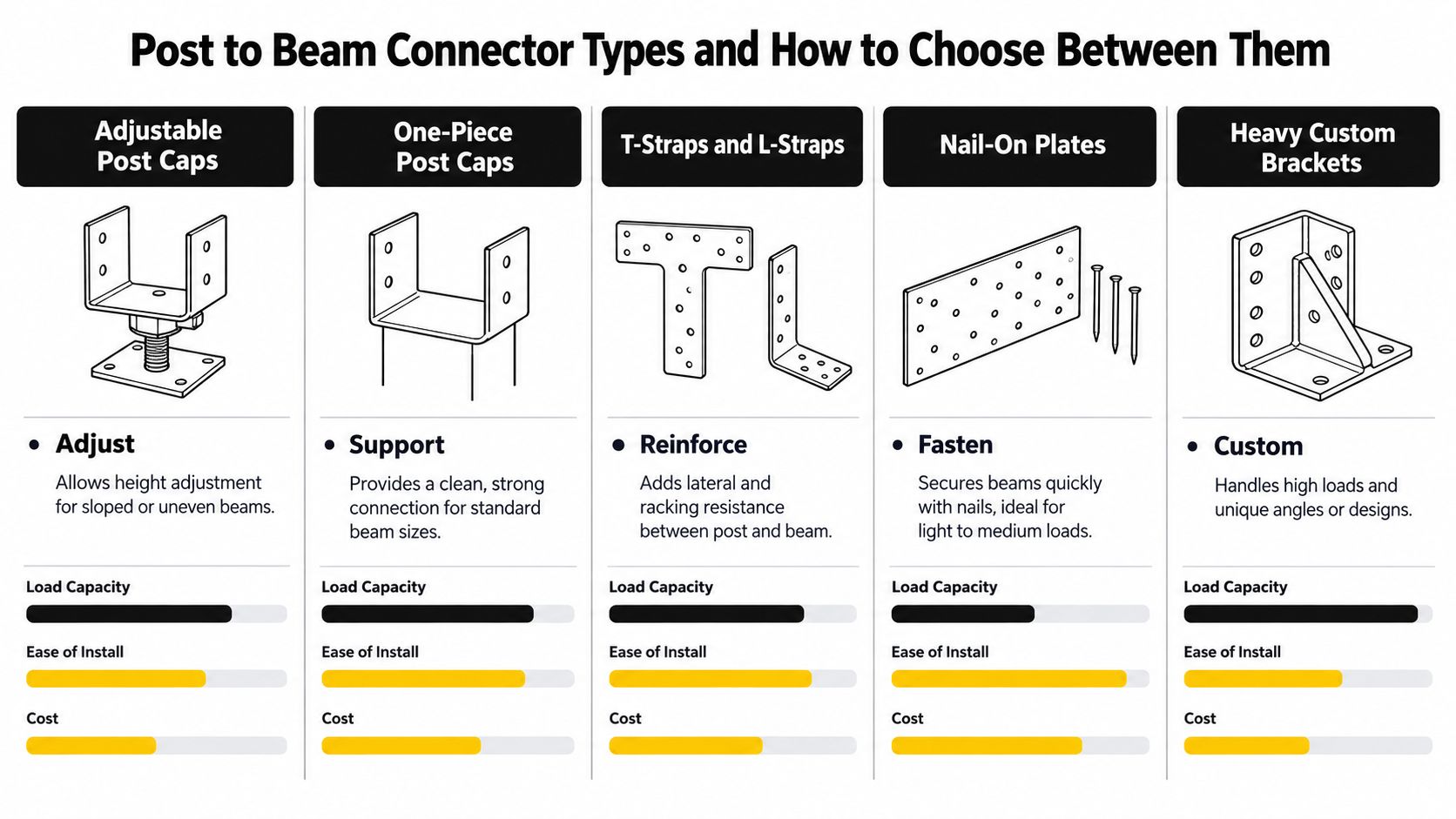
Adjustable post caps
These caps use a configurable geometry or slotted arrangement to accommodate variations in beam width, post orientation, or field alignment. They're useful on retrofit work, out-of-square framing, and projects where a built-up beam doesn't match a standard catalogue dimension.
The trade-off is that adjustability doesn't remove the need to verify the manufacturer's permitted configuration. A cap may adjust physically but have different allowable values depending on how much of the seat is engaged and which holes are used.
One-piece post caps
A one-piece cap is the clean choice for a known post and beam combination. It generally installs quickly, keeps the beam seated over the post, and avoids the loose parts that can be misplaced during framing.
Use it when the actual post width, beam width, and beam depth match the product specification. It isn't a good choice when the timber has been irregularly dressed, the post is twisted, or the beam is wider than the cap seat.
T-straps and L-straps
A T-strap reinforces a connection across a joint, while an L-strap provides restraint around a corner or perpendicular intersection. These are practical for uplift, lateral restraint, and supplemental attachment where the main beam bears on a notch or seat.
They work poorly as a substitute for bearing. A strap can restrain movement, but it shouldn't be expected to support a beam that has no proper seat unless the entire bracket has been designed for that load path.
Nail-on plates
Nail-on plates are compact fittings used where members are close enough for the plate to bridge the joint. They suit lighter framing details, repairs, and locations where a full cap would interfere with the design.
Their limitation is geometry. If members are spaced well apart or the connection carries design loads, Canadian guidance identifies metal post caps, anchors, straps, or nail-on plates as the types of hardware that may be needed, with the selected fitting matched to the actual structural condition. The post-to-post connector range can help when the framing includes aligned posts rather than a simple beam seat.
Heavy custom brackets
Custom brackets make sense for large timber, unusual angles, multi-beam intersections, or architectural connections that standard caps can't accommodate. They allow the engineer or fabricator to control bearing, bolt layout, concealed hardware, and load direction.
They also demand the most documentation. Don't choose a custom bracket by plate thickness alone. Confirm the steel or stainless specification, weld details, hole pattern, fastener schedule, wood bearing, and corrosion system as one assembly.
Dimensional Specs and Sizing for Common Lumber Combinations
Sizing starts with a tape measure, not a nominal lumber label. A post sold as a 6×6 may not measure the same as another 6×6 after dressing, drying, or treatment. Built-up beams introduce another variable because the outside width depends on the number and thickness of the plies, not just the beam's description.
Read the specification in this order
Measure the actual post. Record width and depth, and check whether the post is square. A true 6×6 connection has different geometry from a dressed post that only carries the nominal label.
Measure the beam assembly. Check the total width, depth, ply alignment, and whether the plies are flush. A double 2x beam and a single 4x beam can have different bearing and fastening requirements even when their overall dimensions appear similar.
Check the connector seat. The seat must support the beam without forcing the metal to twist. Verify seat width, seat depth, flange height, and clearance around any beam projection.
Confirm the hole pattern. The fastener holes must land in sound wood with the specified edge and end distances. Don't shift the bracket casually because the supplied holes miss a knot or fall at the edge.
Compare the listed configuration. If the catalogue lists a post and beam combination that matches the measured timber, use that configuration. If not, select an adjustable or engineered alternative rather than guessing.
California guidance requires deck beam connections to wood posts to transfer vertical loads and resist horizontal displacement. It also requires manufactured post-to-beam connectors to be sized specifically for the post and beam dimensions. Where posts bear on concrete footings, lateral restraint must come from manufactured connectors or from a minimum 12 in. post embedment in surrounding soil or concrete piers, as described in the California residential code connection provisions.
Post to Beam Connector Sizing Quick Lookup
| Post Size | Beam Configuration | Connector Seat Size | Recommended Type |
|---|---|---|---|
| 4×4 | Single beam with confirmed actual width | Match measured beam width and bearing depth | One-piece post cap |
| 4×6 | Beam wider than the post | Match beam width, with full post engagement | Fixed cap or adjustable cap |
| 6×6 | Double 2x beam, flush plies | Match the built-up assembly, not the label | Adjustable cap or sized post cap |
| 6×6 | Single 4x beam | Match actual beam width and seat depth | One-piece cap or heavy bracket |
| 6×6 | Irregular or out-of-square framing | Adjustable geometry with approved hole use | Adjustable post cap |
| Built-up beam | Multiple aligned plies | Seat must support the complete assembly | Heavy cap or engineered bracket |
A connector that fits over the post but leaves part of the beam unsupported isn't correctly sized. If the beam rocks in the seat, stop and resolve the geometry before fastening.
Load Capacities and Understanding Allowable Design Values
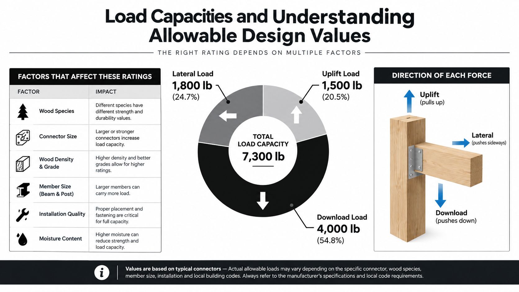
A connector schedule should start with the forces, not the product photograph. The beam sends downward load into the post, wind or seismic action can create uplift, and lateral forces can try to slide the beam across the post. Each direction may have a different allowable value, and the wood, fastener, connector, and supporting foundation can govern independently.
Allowable stress design values are not interchangeable. A manufacturer's table may separate download, uplift, and lateral resistance, and those values depend on the connector configuration, timber dimensions, wood species, fastener type, and installation pattern. If a fitting is expected to carry design loads, follow the manufacturer's load recommendations rather than substituting a similar-looking screw or omitting holes.
Trace the load path
Start at the decking and floor framing. Determine how that load reaches the beam, then follow the beam into the connector, the post, the post base, the anchor, and finally the footing or foundation. The connector can't be judged in isolation if the post base permits lateral movement or the concrete anchor lacks the required embedment and edge distance.
For a deck beam, compare the connector's allowable values with the reaction at the post location. Check the most demanding post, usually one supporting the largest tributary area or an unfavourable beam intersection. Then check the wood around the fasteners, because a thick bracket doesn't prevent splitting, withdrawal, crushing, or tear-out in the timber.
The California deck lateral-load provisions require hold-down tension devices in not fewer than two locations per deck, located within 24 inches of each end, with each device rated for at least 1,500 pounds allowable stress design capacity. An alternate prescriptive detail allows four locations per deck, with each device rated at least 750 pounds. Those devices form part of the lateral system. They don't turn an undersized post cap into an adequate beam connection.
Use the manufacturer's table as an installation document, not as a marketing figure. Confirm the tested or listed timber condition, fastener length and quantity, direction of force, and any limits on notches, edge distances, or built-up members.
Materials Finishes and Corrosion Protection for Canadian Climates
A connector that survives a dry inland porch may not be the right choice for a coastal deck or a structure exposed to winter road salt. Finish selection is a design decision, especially where pressure-treated lumber, wet service, splash water, or airborne salt keeps the metal damp for long periods.
Canadian technical literature treats corrosion classification as a required design step. It also identifies hot-dip galvanized or stainless steel for connectors and fasteners exposed to treated wood or severe conditions, while pointing out that consumer guidance often stops at size and ignores finish, service life, and failure modes across different climates. See the Canadian connector corrosion guidance before finalising the hardware package.
Finish choices in the field
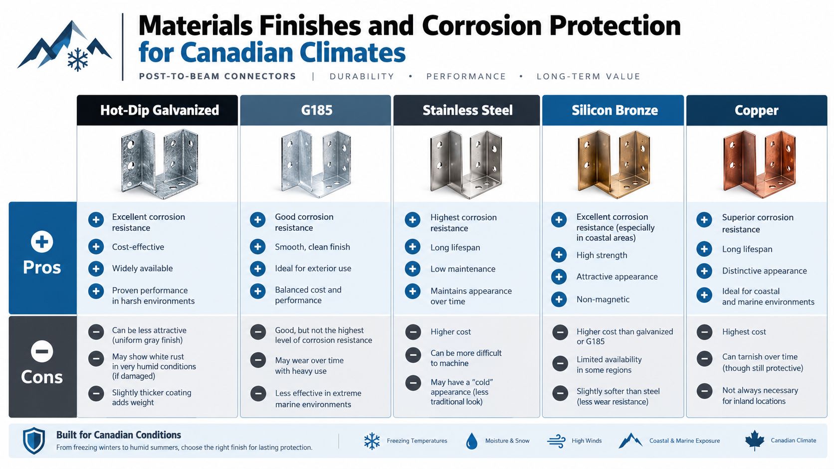
Hot-dip galvanized steel is a practical baseline for many exterior deck conditions. The zinc coating provides useful corrosion resistance, but damaged areas, cut edges, incompatible fasteners, and trapped moisture can still become failure points.
G185 galvanized coatings are commonly considered where a heavier zinc coating is needed than standard galvanizing. Verify that the connector and fasteners are specified as a compatible system, because a highly protected bracket paired with an unsuitable screw creates a weak point at every hole.
Stainless steel is the conservative choice for severe exposure, coastal conditions, and treated-wood contact when the product specification calls for it. It generally costs more and can gall during installation, so use the correct driver technique and don't mix grades casually.
Silicon bronze and copper have specialised corrosion-resistance applications and can suit particular architectural or marine-adjacent details. They aren't interchangeable with every structural connector, and their mechanical properties, compatibility, and availability must match the design.
California corrosion guidance permits hot-dipped zinc-coated galvanized steel, stainless steel, silicon bronze, and copper for fasteners and connectors in contact with preservative-treated or fire-retardant-treated wood. Zinc-coated fasteners must meet ASTM A153 minimum coating-weight requirements, while stainless-steel driven fasteners must meet ASTM F1667 material requirements, as outlined in this California fastener corrosion reference.
For Canadian projects, compare coastal British Columbia, Ontario winter salt exposure, and wet-service conditions separately. Xtreme eDeals' stainless steel fastener selection is one place to compare compatible fasteners, but the connector manufacturer's instructions and local code requirements still control the final choice.
What doesn't work
Painting over a corrosion-prone connector after installation isn't a substitute for the specified finish. Neither is pairing stainless screws with a bare or incompatible bracket and assuming the entire assembly has stainless performance. The coating, connector, washer, bolt, screw, and treated timber must be considered together.
Code and Inspection Considerations for Positive Connections
Inspectors usually aren't looking for the largest piece of metal on the truck. They're checking whether the connection matches the approved detail, whether the fasteners occupy the specified holes, and whether the load path continues into the post base and foundation.
In Canada, post-and-beam connections are governed through the National Building Code of Canada and CSA O86. Canadian Wood Council guidance identifies post-and-beam structures as designed under CSA 086 or CSA O86, with Part 9 of the NBCC providing general residential requirements. Where members are spaced well apart, the connection may need metal post caps, anchors, straps, or nail-on plates, and manufacturer load recommendations should be followed when the fitting carries design loads. The Canadian Wood Council post-and-beam notes provide the relevant technical context.
Prepare the permit detail
Show the post size, beam configuration, connector model or approved equivalent, finish, fastener type, and installation orientation. A drawing that says “bolt beam to post” leaves too much unresolved. The reviewer needs to understand how the joint resists vertical load, uplift, and lateral movement.
On California decks, beam connections to wood posts must transfer vertical loads and resist horizontal displacement. Public-agency guidance also emphasises positive post-to-beam attachment, often using metal straps and clips, and calls for approved manufactured post cap and post base cap connectors in the submittal package. Where the jurisdiction specifies it, through-bolting or another non-withdrawal attachment method must be used rather than relying on an informal screw pattern. The Daly City deck planning guide illustrates how those requirements appear in practical permit documentation.
Inspect the installed joint
Before covering the connection, check that the beam is fully seated, the post is plumb, the bracket isn't bent, and every required fastener is installed. Look for split wood at the end grain, screws driven outside the pre-punched holes, washers bearing on uneven surfaces, and post bases that allow the column to slide.
A notched-post connection can be acceptable when properly designed and executed. A cap-mounted beam can also be appropriate. Neither approach works if the notch is oversized, the remaining post section is compromised, or the cap is being used outside its listed dimensions.
Fastener Schedules and Installation Best Practices
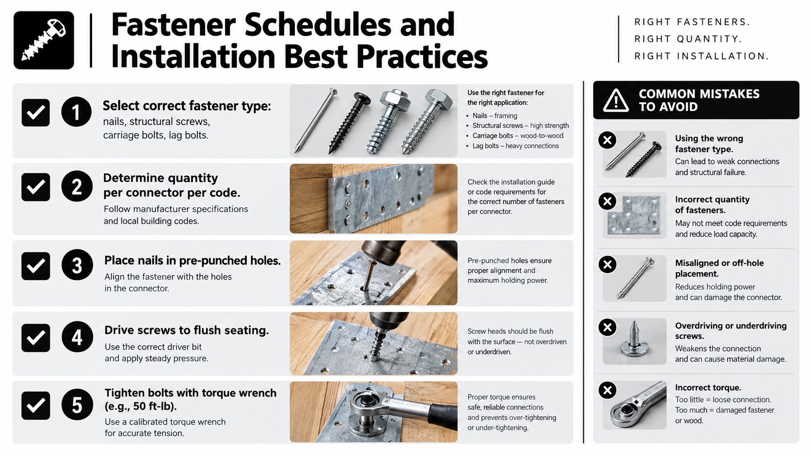
Fasteners are part of the connector, not an accessory added after the metal is chosen. The correct bracket with the wrong screw length can fail through withdrawal, inadequate penetration, corrosion, or timber splitting. Substituting a generic deck screw for a listed structural fastener is one of the fastest ways to invalidate the connection.
Canadian deck and handrail guidance requires positive connections where posts and beams support floor framing, with resistance to uplift and lateral displacement. Beam-to-post details may use notched posts or post caps. The same guidance gives a concrete joist-end lateral-restraint minimum of 3 nails of 10d size, 3 in. x .128 in., or 3 #10 x 3 in. wood screws, demonstrating that code-based practice can specify exact fastener quantities rather than leaving the joint open to interpretation. The Canadian deck connection presentation sets out that fastening example.
Install in a controlled sequence
Dry-fit the connector. Set the cap or bracket over the post and place the beam into the seat. Confirm the timber doesn't force the flanges outward and that the fastener holes land in solid wood.
Plumb and align the post. Use a level on two adjacent faces. Correct the post before fixing the beam, because a skewed post transfers eccentric force into the connector.
Seat the beam completely. The beam should bear on the intended seat or notch, not on a flange edge or a screw head. Remove debris and trim proud treatment or splinters that prevent full contact.
Start the specified fasteners. Use the manufacturer's listed nails, structural screws, bolts, washers, and anchors. Fill the pre-punched holes unless the approved detail specifies otherwise.
Drive fasteners flush, not buried. Overdriving reduces the effective bearing area and can damage corrosion protection. Underdriving leaves the connector loose and may prevent the head or washer from bearing properly.
Complete the lateral system. Add straps, clips, through-bolts, or post-base restraint where the design requires them. A beam cap can't compensate for a post that slides at the footing.
The installation sequence matters because tightening one side fully before the beam is seated can pull the connector out of square. Work symmetrically, recheck alignment, and then inspect the completed joint from every accessible face.
Practical check: Count the installed fasteners against the product schedule. Don't count empty holes as future capacity.
For bolts, use the specified diameter, length, washer arrangement, and tightening method. For concrete anchors, confirm the anchor type, embedment, edge distance, and substrate condition. If the connector schedule calls for through-bolting, don't replace it with surface screws because the screw gun is already in hand.
Troubleshooting Common Issues and Quick Reference Resources
A beam that rotates, a cap that will not seat, or rust streaks below the joint are early warnings. Correct them before decking conceals the connection.
Diagnose the symptom
| Field symptom | Likely cause | Corrective action |
|---|---|---|
| Beam rotates in the cap | Seat too wide, incomplete bearing, or missing lateral restraint | Recheck actual dimensions and complete the specified restraint |
| Connector will not seat | Nominal size used instead of actual size, twisted post, or built-up beam mismatch | Measure the timber and select a compatible or adjustable cap |
| Fastener blows out the side | Hole pattern, edge distance, or fastener length is wrong | Stop, check the specification, and reposition only under an approved detail |
| Rust streaks appear below the joint | Finish or fastener package is unsuitable for exposure or treated wood | Replace compromised hardware with a corrosion-resistant system that matches the exposure |
| Inspection flags the joint | Unapproved fitting, missing fasteners, or incomplete load path | Match the approved drawings and manufacturer schedule before covering the work |
Do not force a mismatched connector with a grinder or torch. If a required hole falls over a split or knot, do not create a new pattern without confirming the revised detail. The repair may call for another connector, a strap, a through-bolt, or an engineered bracket. In Canadian coastal, wet, or heavily treated-wood exposures, check the connector finish and fastener coating together. A corrosion-resistant bracket paired with incompatible fasteners can still fail inspection or deteriorate at the joint.
Keep a small reference set
Keep the connector drawing, installation instructions, fastener schedule, finish specification, and permit detail in the site folder. Store related information for post bases, joist hangers, anchors, straps, and uplift devices nearby. The post-to-beam joint is only one part of the load path, and positive-connection requirements often depend on the surrounding hardware.
For product sourcing, XTREME EDEALS INC. carries deck and fence hardware, including post bases, beam seats, uplift hardware, lateral connectors, fasteners, anchors, and Decorex Hardware post caps and brackets. The catalogue at XTREME EDEALS INC. includes construction hardware for DIY and professional projects. Product details can help you reorder matching components instead of combining incompatible finishes or fastener systems.
Before closing the framing, compare the measured timber, connector specification, and installed fasteners. Count every required fastener and verify the correct type, length, washer, and coating. If those items do not agree, the connection is not ready for inspection or concealment.