
You've finished setting the posts, cut a neat batch of balusters, and the railing looks evenly spaced from the ground. Then the inspector brings out a rigid test sphere, and one end bay fails because the clear opening is wider than it appeared. That mistake can mean removing finished pieces, filling holes, and rebuilding a rail that looked right at a glance.
Spindle spacing on deck projects is less about repeating a convenient measurement and more about controlling the actual open space between installed parts. The width of the baluster, the post-to-baluster gap, the bottom rail, coatings, angled cuts, and movement under load all matter. The layout also needs to work with the required guard height and the way the rail is supported.
This guide treats the railing like a builder lays it out in the field: measure the bay, calculate from real dimensions, centre the pattern, use a simple jig, and test the finished work. For broader project ideas and practical renovation notes, you can also follow our latest blog updates from TimberLodge365.
Why Spindle Spacing Matters Before You Cut Anything
A railing can look perfectly balanced and still fail when the test sphere reaches an end bay. The common mistake is laying out balusters by centre-to-centre distance, then treating that number as the permitted opening. Inspection concerns the clear opening, measured between finished surfaces. That includes the space beside a post and the gap below the bottom rail.

End bays cause more failures than the middle of a run. A builder divides the full bay by a convenient increment, installs the pattern, and finds that the last opening is wider than the rest. The same problem appears after paint or stain changes the finished spindle width, or when angled cuts and post connections reduce the expected clearance.
Measure the installed surfaces, not just the stock written on the cut list. Under load, a flexible rail or cable assembly can shift slightly, so check the opening with the system supported as it will be in service. Cable layouts also need a separate check at the bottom rail and around end fittings, where the cable may deflect or leave a larger opening than it does in the middle.
The layout affects more than appearance
Even spacing gives the railing a deliberate rhythm, but it also leaves room for brackets, fasteners, corners, and rail movement. Overly tight areas create unnecessary cutting and can crowd hardware. A sound layout makes the posts, spindles, rails, and corner conditions work as one assembly.
The required guard height is part of that assembly. The spindle field must be checked against the complete guard geometry, including the bottom-rail gap, rather than treated as a decorative panel. For broader project ideas and practical renovation notes, you can also follow our latest blog updates from TimberLodge365.
Practical rule: Do not cut the full spindle batch until one complete bay is measured, installed, and checked with the test sphere.
Use a story stick to mark centres, then dry-lay the pieces before fastening. Check the first and last openings, the tightest middle opening, the bottom-rail gap, and any cable or corner transition. That short setup prevents wasted material and catches the failure points that a tape measure alone can miss.
Code Requirements for Deck Spindle Spacing You Must Meet
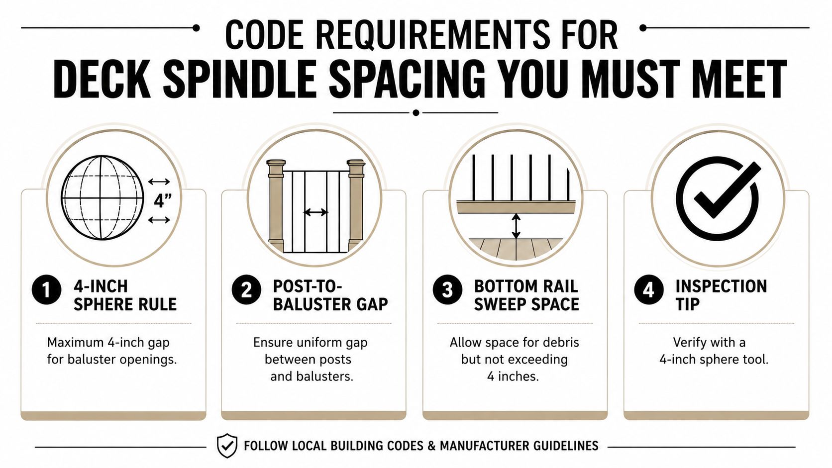
California's governing residential guard rule uses a 4-inch sphere test. Openings between balusters must not allow a sphere with a 4-inch diameter to pass through, and the same limit applies between a post and a baluster. The opening is what matters, not the centre-to-centre dimension printed on a layout sketch. California stair and baluster guidance describes the same standard for the bottom rail gap above the deck surface.
That means a layout can fail in three different places:
- Between infill members: The clear opening in the vertical baluster field must stay below the sphere limit.
- At posts: The first or last baluster can leave a wider opening beside a post if the bay wasn't calculated separately.
- Below the bottom rail: A correct vertical field doesn't compensate for an excessive sweep space beneath the rail.
Stairs use different opening limits
Stair layouts need their own check. California residential guidance allows a 4-3/8-inch sphere at the open side of stairs, while the triangular opening formed around the tread, riser, and bottom rail has a 6-inch sphere limit. Residential code guidance identifies these stair limits separately from the guard opening requirement.
Don't carry a level-deck layout blindly onto a rake. The baluster angle, tread relationship, and triangular space can change the result even when the individual pieces appear evenly distributed. Mark the stair geometry on the actual rail or use a full-size template before drilling.
Height and spacing belong to one inspection
A guard that's correctly spaced but incorrectly proportioned can still create a problem. Confirm the required guard height, rail attachment, post stiffness, and infill openings as one assembly. California's historical code treatment can allow some existing historic railings and baluster spacing to remain where no distinct hazard is identified or created by a change in use or occupancy, but that exception doesn't turn a new installation into an exempt one. California Historical Building Code guidance also reflects the broader principle that infill spacing is treated as a measured safety condition.
For the final check, use a rigid sphere rather than relying on a flexible tape measure or visual estimate. Test the centre openings, post transitions, bottom rail, corners, and stair triangles after all parts are fastened.
For a concise reference focused on the same subject, see this baluster spacing code guide.
How to Measure and Calculate Spindle Spacing Correctly
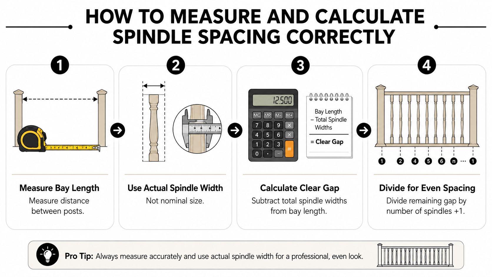
Start with the clear bay length, not the overall deck length. Measure between the inside faces of the posts where the balusters will sit. If a rail has a cap, trim, or blocking that changes the usable field, measure the surface that receives the spindles.
Next, measure the baluster width. A common square baluster may be described as 1.5 inches, and practical guidance indicates that it typically needs about 3.5 inches of clear space between pieces to satisfy the opening rule. San Diego deck railing guidance explains why centre-to-centre spacing alone isn't enough.
Use the bay calculation
For a bay with:
- a measured inside length of L
- N balusters
- an actual baluster width of W
- and N + 1 clear spaces, including both end spaces
the even clear gap is:
Clear gap = (L − N × W) ÷ (N + 1)
Don't treat that equation as permission to use the largest possible gap. Choose a baluster count that leaves a clear opening below the applicable limit, then check the result against the actual installed parts.
A worked example makes the process easier. Suppose the measured bay length is L, and the selected square balusters measure 1.5 inches wide. If you choose N pieces, subtract the combined width of those pieces from the bay, then divide the remaining length by N + 1. If the resulting clear gap is wider than the permitted opening, increase the baluster count. If it is much tighter than necessary, you can compare the appearance and installation effort with a lower count, provided the opening remains compliant.
Protect the end bays
The end spaces are part of the calculation. Don't divide only the gaps between balusters and then force the leftover space beside the posts. That produces the classic layout with a narrow opening on one end and a wide opening on the other.
A story stick helps. Mark the post face, first clear space, baluster centre, repeated spacing, and opposite end on a scrap strip. Transfer those marks to every matching bay. For a different bay length, make a new story stick instead of stretching the old pattern.
Coatings and angled cuts deserve another measurement. Paint can reduce clearance, while a bevel or rake cut can create a larger opening at a corner. Measure the finished parts where the sphere will travel.
For related outdoor planning, you can find the right deck board gap with a separate calculator. For spindle calculations, use the baluster spacing calculator as a checking aid, then confirm the result against the installed rail.
A visual walkthrough can help before you mark a long run:
Laying Out Even Spacing Across Bays Corners and Stairs
A railing rarely runs as one uninterrupted line. Posts break the length into bays, corners change the viewing angle, and stairs introduce a rake. Lay out each bay from its actual inside faces, then keep the clear openings and visual rhythm consistent across the complete railing.
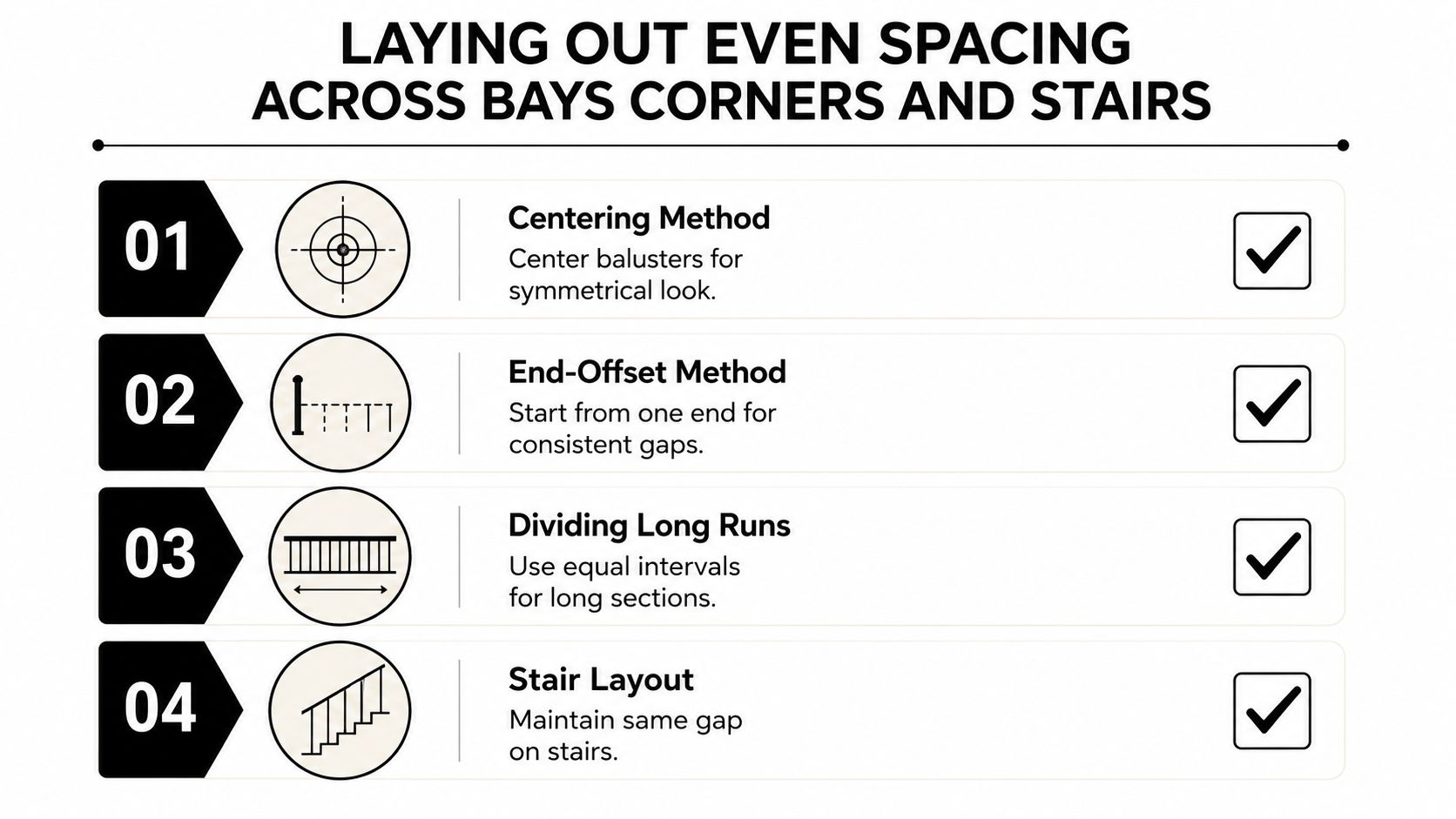
For a short, visible bay, centre the pattern between the posts. Calculate the required clear openings first, then distribute any harmless remainder between both end offsets. This keeps the first and last openings comparable. At a corner, protect the corner post and check both adjoining bays together. A balanced corner looks intentional, while one tight side and one loose side remains noticeable even when each opening meets the limit.
Break long runs into controlled bays
Long runs need support points that also establish the calculation boundaries. Use the post intervals from the applicable code guidance to define each bay before calculating infill spacing. California deck guard guidance explains how support layout relates to guard performance.
Set the posts first, measure between their finished inside faces, and mark a centre line for every section. A single tape mark carried across several bays allows a small error to spread through the entire run. Separate measurements account for ordinary construction variation.
Dry-lay the balusters on the rail before drilling. Check the first and last pieces against the neighbouring bays, inspect the corner balance, and confirm that brackets or fasteners will not obstruct the marks. This check also exposes an incorrect clear-opening assumption before holes are made.
Cable and stair transitions need movement checks
Cable railings require a load check, not only a visual measurement. A narrow opening can widen as the rail, post, or cable assembly flexes under pressure. Tension adjustment may reduce movement, but excessive tension can place unwanted stress on posts and fittings. Measure the clear opening in the finished, adjusted system, including the cable and bottom-rail gaps that can be overlooked during layout.
Stair transitions need a full-size trial. Mark the rake line, position the balusters, and inspect the open side plus the triangular spaces near each tread and riser. Keep the pattern deliberate, while applying the stair limits to every relevant opening instead of copying the flat-deck layout. Check the first and last stair bays after the rail is fastened, because tightening the assembly can shift end clearances.
Tools Jigs and Installation Tips for Different Spindle Types
A reliable spindle layout starts with ordinary tools used consistently. Keep a sharp tape measure, level, speed square, pencil, drill or driver, clamps, and a rigid test sphere at the work area. A story stick made from straight scrap is often more useful than repeatedly reading a tape because it transfers a complete pattern without accumulating small marking errors.
Make a spacer jig that represents the approved clear opening, not the centre-to-centre distance. For square wood balusters, cut the jig to sit between the actual installed faces. Use it while dry-fitting, then check the first completed bay before repeating the marks.
Wood and metal balusters
Wood pickets benefit from pre-drilling, especially near ends where splitting can push a baluster out of position. Keep the bottom rail level and verify its sweep space before fastening the infill. Metal balusters need accurate hole locations and compatible inserts or brackets, since a small marking error can make the pattern drift across the bay.
For installation sequencing, this guide to installing balusters on a deck can supplement the physical layout work. Keep fasteners centred, avoid forcing a piece into a mis-sized opening, and recheck the rail after the screws draw the parts tight.
Cable railings
Cable systems require more than a visual gap check. Permit Sonoma states that residential guardrails must satisfy the 4-inch sphere rule, with cables at least 1/8 inch in diameter and spaced no more than 3.00 inches apart, measured between the inside edges of adjacent cables. Permit Sonoma's cable rail bulletin provides that specific installation direction.
Oakland guidance is also more specific than many general railing summaries, calling out 3.5-inch maximum cable spacing and 4-foot maximum support spacing. Oakland's cable railing handout is useful when a cable layout needs a local reference.
Use the manufacturer's tensioning sequence, then test the finished system. Check end bays, post deflection, cable sag, and the bottom rail. For unusual architectural components or digitally modelled parts, architecture industry 3D printing services may be relevant during design development, but the installed railing still needs physical verification.
XTREME EDEALS INC. supplies options that can fit this workflow, including balusters, post caps, brackets, deck screws, and related railing hardware. Select parts by the actual post, baluster, and rail dimensions rather than by appearance alone.
Final Checks and Pro Tips for a Compliant Finished Railing
Fastening can change a careful layout. Screws may pull components out of line, coatings can reduce clear openings, and cable tension can move posts or increase sag. Inspect the installed railing after all parts are secured and finished.
Use this final routine:
- Test every opening: Pass a rigid sphere through the baluster field, post transitions, corners, and stair sections.
- Check the bottom rail: Measure the gap below it after installation, including surfaces, trim, and angled cuts.
- Re-measure finished surfaces: Account for paint, stain, inserts, and any coating that reduces clearance.
- Inspect end bays: Compare both end openings with the middle. End bays often change because posts and rails flex differently.
- Load the cable system: Apply normal pressure, then check tension, post movement, sag, and the opening between cables.
Record clear opening measurements, not just center-to-center spacing or nominal product dimensions. Check cable and bottom-rail gaps separately, since a compliant baluster layout does not prove every opening is acceptable. Treat each stair transition as its own condition.
A finished railing should stay even and secure under use. Source balusters, connectors, post caps, and fasteners from XTREME EDEALS INC. at xtremeedeals.ca, then complete the installation with a measured layout and final sphere test.
XTREME EDEALS INC. also offers brackets, deck screws, and related railing hardware for deck projects. Compare the required parts before cutting.