

You're standing at the lumber rack with a nominal 2×8 joist in one hand and a hanger in the other. The label appears to match, but the steel looks too narrow, the seat doesn't reach the joist's full depth, or the nail holes land uncomfortably close to the edge. That small mismatch can stop deck framing, trigger an inspection question, and force you to remove hardware you thought was already installed correctly.
Joist hangers dimensions matter because a connector isn't rated by appearance alone. Width, seat depth, flange height, fastener layout, joist profile, and supporting-member geometry work together. A hanger that fits a piece of dimensional lumber may still be unsuitable for an engineered I-joist, LVL, PSL, or glulam connection. The practical rule is simple: measure the members, identify the tested hanger configuration, then install it with the specified fasteners.
Understanding Why Dimensions Matter
A small deck can stall when a nominal joist size appears to match a hanger, yet the connection does not fit the tested assembly. A generic chart may point to the right label while the hanger leaves too little bearing, puts flange holes near the edge, or conflicts with a ledger face that is not flat. Swapping to another model can also change the nail pattern and installation requirements.
Seat depth controls how much of the joist is supported. Flange height helps restrain the member laterally and limits rotation. Width must suit the joist's actual side-to-side measurement, not only the nominal size printed on the lumber. The header or ledger must provide a sound, flat bearing surface, and its geometry must match the hanger's approved use.
The geometry behind a rated connection
Canadian evaluation records illustrate the gap between a nominal lumber match and tested performance. For a 38 × 140 SPF header and joist assembly, one evaluated metal hanger lists W = 210 mm, H = 22 mm, and D = 39.7 mm, with a factored resistance of 6.0 kN when installed with specified 10d × 1.5 in. nails in the header and joist CCMC evaluation data. Those dimensions and fasteners were evaluated together. Changing the member, support condition, or nail schedule can change whether the connection remains suitable.
The same check matters even more with engineered lumber. An I-joist, LVL, PSL, or glulam may share a nominal depth with dimensional lumber while having different flange, web, or end-bearing requirements. A hanger that slips onto the member is not automatically approved for that member.
Practical rule: Check physical fit first, then confirm the tested member size, support condition, and specified fasteners.
XTREME EDEALS INC. products are relevant when a project requires clearly identified connector dimensions and matching hardware. Use the listed dimensions to verify a model, not to justify substituting one that merely looks close. For broader layout planning, a kitchen bar dimensions guide can help when deck or renovation work connects to a larger outdoor living layout.
Joist Hanger Categories and Standards
The right category comes before the exact model. A face-mount hanger, top-mount hanger, and I-joist hanger may all support a joist, but they transfer forces through different parts of the connection. Start by identifying the joist material and the way it meets the header, ledger, beam, or engineered support.
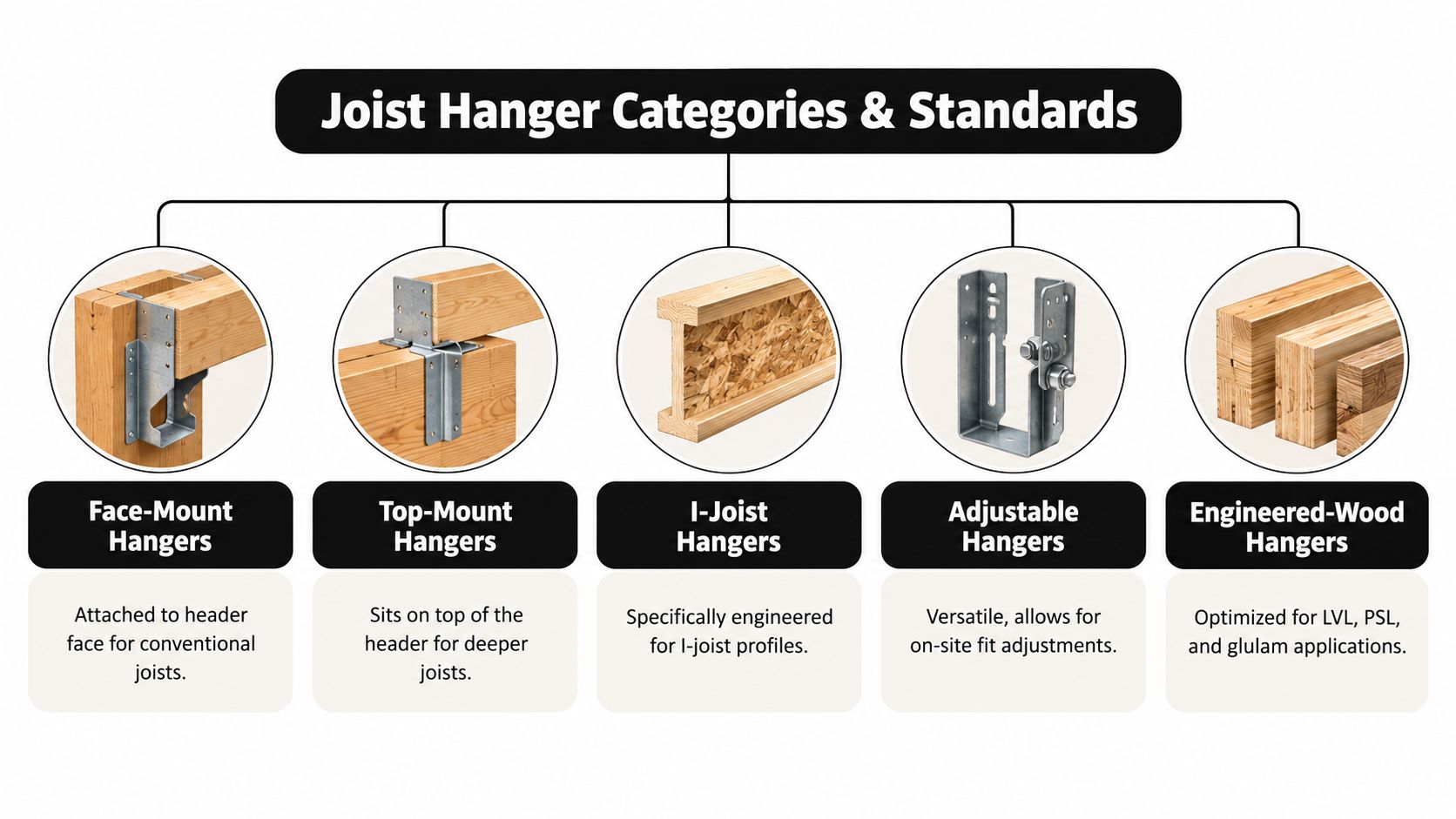
Face-mount hangers
These attach to the face of a ledger or beam and are common for conventional dimensional-lumber framing. Their width generally follows the joist width class, while the vertical body and seat need to support the intended joist depth. A face-mount connector is a poor choice when the joist profile requires web support or when its tested application excludes the member being used.
Top-mount hangers
Top-mount designs sit over the header or beam and may offer a different load path from a face-mounted connector. They're useful where the framing arrangement allows the top flange to bear over the supporting member, but the beam width, joist depth, and surrounding decking must leave room for the installation. A top-mount model can create a fit problem if the beam cap or adjacent framing blocks the flange.
I-joist hangers
I-joists have thin webs and wide flanges, so a dimensional-lumber hanger isn't automatically interchangeable. DSA IR 23-9 requires hangers used with wood I-joists in California applications to comply with ASTM D7147, which addresses testing and allowable hanger loads California DSA IR 23-9 interpretation. The hanger depth, web contact, stiffener requirements, and fastener pattern must correspond to the tested profile.
Adjustable hangers
Adjustable models help address field conditions such as skewed framing or minor alignment changes. They don't eliminate measurement. An adjustable connector still has limits for member width, bearing, rotation, and fastener placement, so use the manufacturer's configuration rather than bending the hardware into an untested shape.
Engineered-wood hangers
LVL, PSL, and glulam members often need deeper or heavier connectors than ordinary joists. Canadian product guidance shows hanger families with seat dimensions around 2 5/8 in. for some 3 1/2 in. joist-width configurations and around 9 1/2 in. for larger engineered-wood hangers, with schedules ranging from 4 to 14 or 16 nails, depending on the model and application Canadian engineered-wood hanger guide.
For a practical selection path, review the joist hangers for decks category only after confirming the member type, actual dimensions, support arrangement, and required fasteners. ICC-ES, CCMC, and ASTM references help establish whether a connector has been evaluated for the intended system. They don't make every similar-looking hanger interchangeable.
Detailed Dimension Charts for Common Hanger Sizes
A dimension chart earns trust only when it matches the actual member and the connector's tested configuration. Nominal labels alone do not establish fit or resistance. The fasteners, supporting material, joist profile, and installation pattern all affect the result.
A Canadian retail listing may identify a hanger for nominal 2 × 6 lumber while giving actual metric dimensions of 90.424 mm width and 44.45 mm length. Check both the label and the steel dimensions before installation. A hanger sold for one nominal size is not automatically suitable for every joist carrying the same label.
Common joist hanger dimensions
The table separates available measurements from items that require verification. The previously mentioned CCMC evaluation covers one specific assembly. It does not establish a universal resistance for every 2×6, 2×8, or 2×10 hanger.
| Joist Size | Width (mm/in) | Seat Depth (mm/in) | Resistance (kN) |
|---|---|---|---|
| 2×6 | 90.424 mm, actual retail listing | 44.45 mm, listed length reference | Verify exact model |
| 2×8 | Verify actual joist and hanger width | Verify exact model | Verify exact model |
| 2×10 | Verify actual joist and hanger width | Verify exact model | Verify exact model |
| 38×140 SPF assembly | 210 mm | 39.7 mm | 6.0 kN |
| CCMC evaluated geometry | W = 210 mm | D = 39.7 mm, H = 22 mm | 6.0 kN |
The 6.0 kN factored resistance applies to the evaluated 38 × 140 SPF header and joist assembly, installed with the specified 10d × 1.5 in. nails in both members. Do not transfer that value to a different hanger, lumber species, joist profile, or nail schedule.
Reading width, depth, and height
Width must hold the joist without forcing it into the connector. Excessive side clearance reduces dependable contact, while an undersized hanger can distort as it is fastened. Seat depth must provide the bearing used by the evaluated configuration, rather than stopping partway beneath the joist. Flange height contributes to lateral restraint and may control the fit around I-joists or deeper engineered members.
The hidden compliance gap appears with engineered and I-joists. A chart can show a nominal depth match while overlooking the required web contact, stiffener condition, or rotation control. Canadian EWP guidance distinguishes between I-joists with and without web stiffeners. Hangers for I-joists without web stiffeners need at least 1/8 inch contact. For stiffened joists, the hanger must support at least 60% of joist depth or address rotation, as described in the Canadian CCMC engineered-wood evaluation.
Use the table for initial screening. Before ordering or fastening, compare the manufacturer's drawing with the measured member, then confirm that the fastener schedule and supporting assembly match the evaluated configuration. A nominal size match is only the starting point.
Measuring Joists and Ledgers for Proper Fit
A hanger can match the nominal lumber label and still fail to fit the actual assembly. Measure the member being installed. Dressed lumber may differ from its stated size, while moisture, planing, swelling, damaged edges, and built-up headers can alter the surfaces supporting the connector.
A four-point field check
Measure joist width. Use callipers at several points, especially near the hanger location. Splits, rounded edges, and local swelling can change the fit. Record the smallest usable width, not only the cleanest section.
Measure joist depth. Check the vertical dimension with a framing square and confirm that the member sits square. For I-joists, record the full profile, including flange and web arrangement. Overall depth does not automatically equal usable bearing area.
Inspect the ledger or beam face. Hold a straightedge against the support and use feeler gauges to find gaps. The hanger needs a sound, reasonably flat face. Shims, crushed sheathing, protruding fastener heads, and uneven cuts can leave the connector bearing incorrectly.
Test the assembly before fastening. Slide the hanger into position and set the joist in place. Check the seat, side flanges, and nail holes. Forcing the joist, bending the hanger, or leaving part of the seat unsupported indicates a fit or model problem. Stop and correct it before fastening.
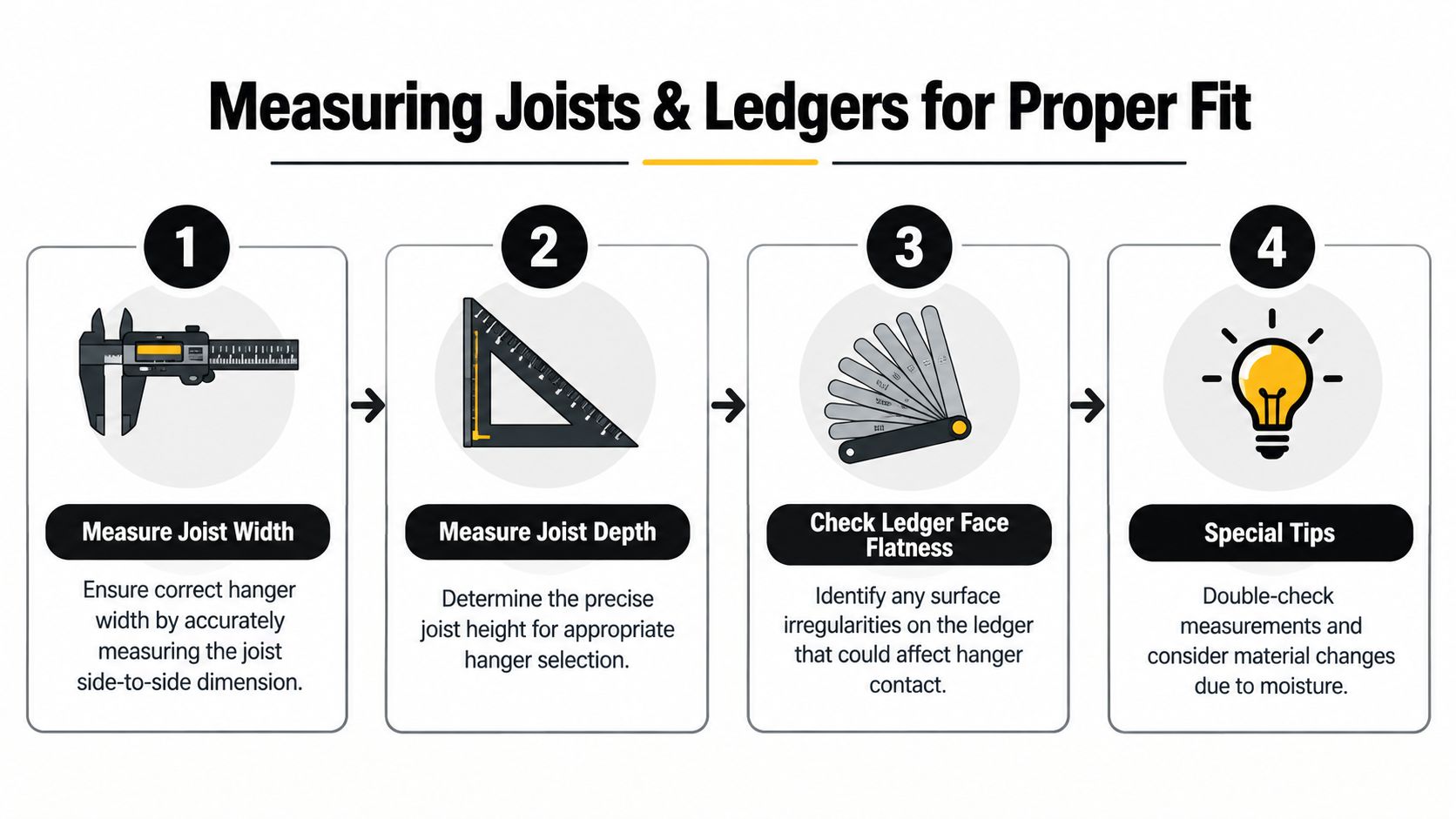
Measure the support as carefully as the joist. A properly sized hanger cannot compensate for a twisted ledger face or a beam connection that leaves its back unsupported.
Spacing changes the layout
Some Ontario municipalities specify tighter joist spacing for composite decking, 300 mm on centre, than for northern species wood, 400 mm on centre, according to the Dufferin County deck checklist and construction guide. Spacing changes the number and placement of hangers, even though it does not change the joist's physical width or depth.
Engineered and I-joists create a compliance gap that nominal-size charts often miss. The measured depth may match the chart while web contact, stiffener requirements, or rotation control remain unresolved. Canadian EWP guidance distinguishes between I-joists with and without web stiffeners. Hangers for I-joists without web stiffeners need at least 1/8 inch contact. For stiffened joists, the hanger must support at least 60% of joist depth or address rotation, as described in the Canadian CCMC engineered-wood evaluation.
Use dimension charts for initial screening only. Compare the manufacturer's drawing with the measured member, then check that the supporting assembly matches the evaluated configuration. If the ledger has rot, movement, or questionable attachment, review when to repair a deck ledger before laying out hanger locations. A sound load path starts behind the connector.
Fastener Requirements and Clearance Guidelines
A hanger can match the joist dimensions and still underperform if the fasteners are wrong, holes are skipped, or nails enter weak edge zones. Published resistance applies to a defined fastener type, length, quantity, and layout. Treat that schedule as part of the connector's working dimensions.
For the Canadian SPF assembly noted earlier, the evaluated installation uses 10d × 1.5 in. nails in the header and 10d × 1.5 in. nails in the joist, with a 6.0 kN factored resistance. That schedule applies to that tested assembly only. Another hanger or wood product may require different fasteners, quantities, or placement.
Place every fastener deliberately
- Use listed fasteners. Connector nails or approved structural screws must match the hanger instructions. Generic deck screws are not an automatic substitute just because the diameter looks similar.
- Keep nails centred. A fastener too close to the joist edge can split the member and reduce connection capacity. Angled driving can miss solid material or deform the hanger.
- Do not overdrive. The head should seat against the connector without cutting into the metal. A crushed hole or distorted flange requires a stop and inspection.
- Fill the specified holes. A hanger can feel tight while remaining under-fastened if the installation schedule is incomplete.
- Check clearances first. Confirm the manufacturer's edge distance, end distance, spacing, and penetration requirements before setting the hanger.
Clearance also depends on the member behind the hanger. A ledger with inadequate edge distance, damaged wood, or crowded existing fasteners may not provide enough room for the specified pattern. Repositioning the hanger does not correct a weak supporting assembly. Confirm the load path and substrate before drilling.
California guidance adds a geometry check: hanger depth must be at least 60% of the joist depth for adequate lateral restraint. A shallow body on a deep joist may appear secure while providing insufficient restraint. That concern becomes more pronounced with engineered and I-joists, where web contact and stiffener details can matter even when nominal dimensions match.
Before ordering, compare the hanger schedule with the manufacturer's approved fasteners and the available clearance. The joist hangers screws selection can help identify compatible hardware, but the product listing does not replace the hanger's installation instructions.
Code and Load Considerations in Canada and California
A hanger can match the nominal size of a joist and still fail to match the tested assembly. That compliance gap matters most with engineered lumber and I-joists, where flange width, web support, stiffeners, fasteners, and rotation control may govern the connection. Canada and California address the same load path through different evaluation and code frameworks, so a dimension chart alone cannot approve the installation.
Canadian evaluation focuses on the complete system
A Canadian evaluation for a 38 × 140 SPF assembly records W = 210 mm, H = 22 mm, D = 39.7 mm, a 6.0 kN factored resistance, and a specified 10d × 1.5 in. nail schedule CCMC Canadian evaluation. Those values apply to the documented combination, not to every hanger with a similar footprint. Connector geometry, lumber size, fasteners, and resistance must be checked as one assembly.
For I-joists, Canadian guidance distinguishes between joists with and without web stiffeners. Hangers without web stiffeners need at least 1/8 inch contact. Stiffened joists require support covering at least 60% of joist depth, unless the design addresses rotation CCMC EWP guidance. A generic 2×10 chart does not establish either condition.
California ties dimensions to tested performance
California DSA IR 23-9 requires wood I-joist hangers to comply with ASTM D7147 for testing and allowable hanger loads. It also requires lateral and rotational support at bearing points located no more than 12 inches from supports when joist hangers are used California DSA IR 23-9 information. Hanger depth, support location, fastener spacing, and edge distances therefore need to match the qualified configuration.
Product dimensions show why one footprint cannot cover every connection. A Simpson Strong-Tie LUS26Z is listed at 4-3/4 in. by 1-9/16 in., while the LUS28Z is listed at 6-5/8 in. by 1-9/16 in. LUS26Z dimensional listing and LUS28Z dimensional listing. Confirm the exact model, joist profile, species, fastener schedule, and approval together.
California residential code materials require approved joist hangers where joists frame into the side of a beam or ledger. Joist, beam, or girder ends need at least 1 1/2 inches of bearing on wood or metal, or at least 3 inches on masonry or concrete, unless approved joist hangers provide support California residential floor framing code. For header joist to trimmer joist connections, approved hangers are required where the header span exceeds 6 feet, or 1829 mm California roof and ceiling framing code.
Structural insight: Select the connector from the code trigger, member profile, and tested load path. Do not make the framing fit a hanger chosen from a nominal-size chart.
Renovation projects also benefit from structural insights for Greater Boston remodels, although California or Canadian requirements govern the actual work.
Installation Best Practices and Common Pitfalls
Installation starts before the first nail. Set the hanger against the ledger or beam, place the joist into the seat, and inspect the contact on every side. The connector should sit square and flush without relying on bent tabs, improvised shims, or force from the fasteners to pull it into alignment.
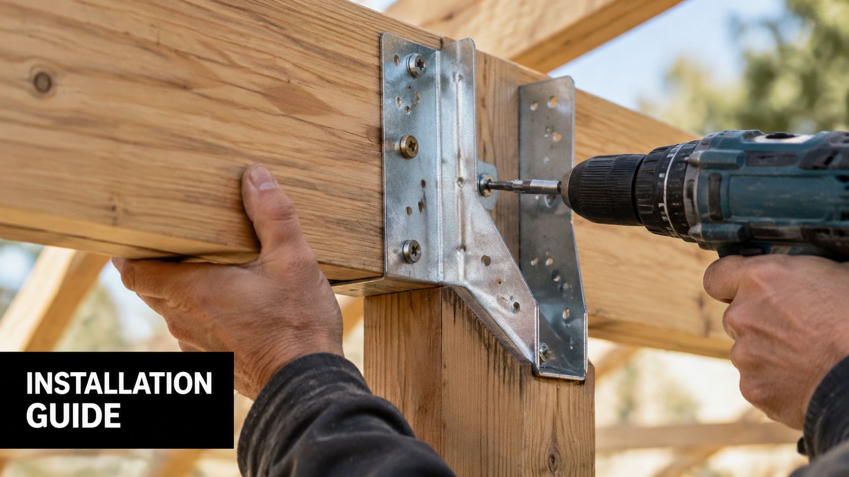
A clean installation sequence
Prepare the support. Remove debris, protruding fastener heads, loose fibres, and damaged wood from the ledger or beam face. Repair a compromised support rather than hiding it behind a connector.
Mark the elevation. Use a level or laser to keep adjacent hangers at the intended joist elevation. A hanger that sits low or high can create uneven decking and introduce unwanted bearing conditions.
Pre-fit the joist. Confirm that the joist reaches the back of the hanger, rests on the seat, and doesn't twist. With I-joists, verify flange and web contact against the approved product detail.
Fasten the header side first. Follow the manufacturer's sequence and use only the listed nails or structural screws. Don't use the fastener head to straighten a misaligned hanger.
Secure the joist side. Drive the specified fasteners without over-angling them or crowding the member edge. Replace a connector that has been bent, torn, or deformed.
Inspect before covering. Look for full bearing, filled required holes, correct elevation, and corrosion-compatible hardware.
Where installers go wrong
A common mistake is choosing a hanger that matches the joist depth but not the joist type. An I-joist's web and flanges create different bearing and rotation conditions from solid-sawn lumber. Another is using a standard galvanised connector with a treated-lumber application that calls for a more suitable corrosion-resistant finish. The right coating depends on the lumber treatment, exposure, and product specification, so check the connector documentation rather than relying on colour alone.
Over-angling nails can move the connector away from the support face. Overdriving can enlarge holes or damage the metal. Installing the hanger before correcting an uneven ledger can leave hidden gaps that reduce contact. These aren't cosmetic defects. They alter the load path.
Before closing the framing: Photograph the installed model, fastener pattern, member dimensions, and any engineered-wood detail. Those records help resolve inspection questions without dismantling finished work.
For a practical installation walkthrough, use the how to install joist hangers guide, then compare the actual connector against its manufacturer documentation. The video below can supplement that inspection, but it shouldn't replace the product's approved installation instructions.
Quick Reference Cheat Sheet
Use this at the framing bench or on site before ordering or installing a connector. The fastest mistake is matching a hanger to a nominal lumber label while ignoring the member type and the tested connection detail.
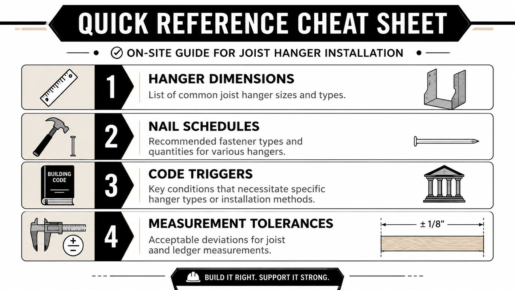
Hanger dimensions
- Dimensional lumber: Measure the actual joist width and depth at the connection, not only the size printed on the order sheet.
- Engineered wood: Identify an I-joist, LVL, PSL, or glulam before selecting the hanger. A nominal depth match does not prove that the connector has a tested fit, bearing condition, or lateral restraint for that member.
- Canadian example: The evaluated SPF assembly lists W = 210 mm, H = 22 mm, D = 39.7 mm, with 6.0 kN factored resistance under its specified nail schedule CCMC evaluation.
- Retail labels: A nominal 2×6 product can still show actual metric dimensions, such as 90.424 mm width and 44.45 mm length. Confirm the product drawing.
Nail schedules
- Specified nails: The cited CCMC example uses 10d × 1.5 in. nails in both the header and joist.
- Approved substitutions: Use only fasteners listed for the selected hanger. A nail that fits the hole may still have the wrong diameter, coating, or penetration.
- Nail placement: Follow the required edge distance, end distance, spacing, and penetration. Keep the full schedule available for inspection.
- Inspection: Replace bent or damaged connectors and correct missing, misplaced, or overdriven fasteners before loading the framing.
Code triggers
- California restraint: Hanger depth must reach at least 60% of joist depth for adequate lateral restraint, subject to the applicable approval.
- California I-joists: Check ASTM D7147 compliance and the required lateral support within 12 inches of supports under the applicable DSA guidance.
- Bearing: Code materials identify 1 1/2 inches of bearing on wood or metal and 3 inches on masonry or concrete unless an approved hanger changes the connection.
- Header trigger: Approved hangers are required for header joist to trimmer joist connections when the header span exceeds 6 feet, or 1829 mm.
Measurement and layout checks
- Ledger face: Check flatness with a straightedge and feeler gauges. Correct gaps or irregular support surfaces before fitting the hanger.
- Joist spacing: Some Ontario municipal guidance specifies 300 mm on centre for composite decking and 400 mm on centre for northern species wood.
- I-joist contact: Confirm the required web or stiffener contact before fastening. A hanger that fits the flange width can still fail the approved engineered-wood detail.
- Final decision: If the dimensions fit but the tested application does not match, do not install it.
XTREME EDEALS INC. lists joist hangers with dimensions, along with deck screws, nails, washers, bolts, and other framing hardware. Compare the connector and fastener specifications before ordering, then verify the selected products against local code and the manufacturer's installation detail.